In the clients and server game I am developing, I need to recognize which player the client is.
So I pass the player number I set in the server to the client using a SyncVar.
However, there is a problem.
If you set the player number in the server, it will be overwritten by the server itself to it’s default value.
Why is that?
The reason is that the initialization of SyncVar happen somewhere after your player Object was already initialized locally. So setting the player number value right after Initialize() might be overwritten once the player is spawned.
In order to overcome this you need to send a message from the server to the client with the Player Number when the server adds the player.
Once the client’s player has spawned he can call a Cmd to update the player number on the server(the number it received from the server with a message).
(Kind of complex, not sure if there is a better way to do this identity synchronization)
What’s wrong with this code is that msg.player1 might not be what we want, because go.GetComponent<NetPlayer>().player1 is SyncVar and might get it’s default value overwrite the value we have just set.
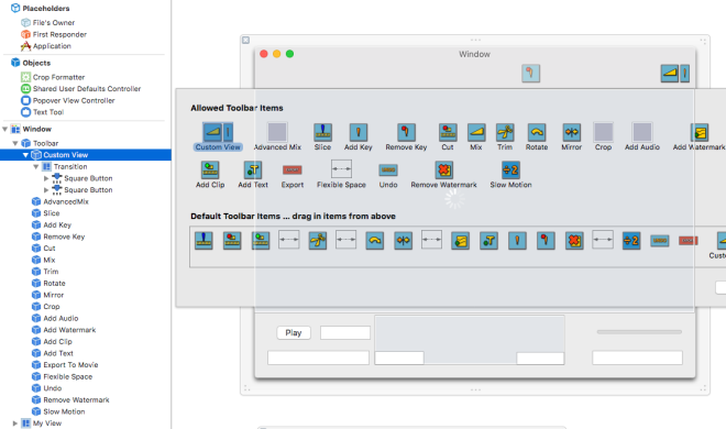
This kind of toolbar can be easily made using xCode’s interface builder.
In the interface builder this tool bar looks like this:
Notice all the items are either NSToolBarItem or a Flexible Space.
There is one exception though… the Custom View.
I wanted to make a custom button which also have a drop down button next to it.
There is a way to add custom NSToolBarItem using NSToolBarDelegate.
The problem with using NSToolBarDelegate is that you cannot make use of the order you placed the items using the Interface Builder.
You will have to make a list of the items in code(Or at least I didn’t find a way to not do this in code using the delegate).
If you look at the screenshot above you will see that I also have a Custom View and this Custom View do display in the app in the same order I palced it in the toolbar.
In order to achieve this you need to create an NSView in the same nib your NSToolbar is at.
The NSView’s content will be the custom button itself(in my case I have put two buttons inside, one square and one more narrow for additional options).
After that you only need to drag your off window NSView under your NSToolbar in the interface builder and xCode will create an NSToolbarItem with your own NSView underneath it.
You can then drag the item with the custom view into the default toolbar items area.
However, your custom view will not display in the tool bar this way and will just leave a blank space.
In order to make your custom NSView display we need to set it’s parent’s(the NSToolbarItem) view property to your actual view. I didn’t find a way to do this from within the interface builder so I subclessed NSToolBaritem and did this in code.
For the sake of completion here is the custom NSToolbarItem code(the customView IBOutlet is refernced into your NSView that is under the CustomToolbarItem) :
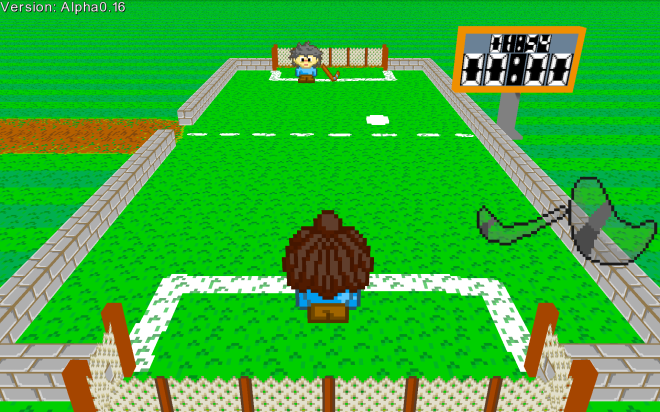
I have been working on a game called Flat Out Hockey for Android, iOS, Mac and OUYA.
For this game I needed both “Touch buttons”(which are buttons mimicking gamepad buttons) and a touch area where you would hold your finger and the character would follow:
It worked fine for the most part, but if I pressed several buttons at once or tried to do crazy tapping and swiping my touch area would stop responding.
All the touches in the game’s iOS version are handled using the touches functions(touchesBegan, touchesMoved, touchesCancelled, touchesEnded).
I would go over all the UITouch of the UIEvent(using [event allTouches]) and track all the touches that have started, moved or ended(there could be multiple of them at once).
What I didn’t realize is that even when you are inside the touchesEnded function(for instance) you may get UITouch which did not actually end.
I am thinking that maybe UIEventallTouches give all the current touches regardless which touches function has been called, which means you always need to check for the UITouchPhase of every UITouch!
This is quite simple and makes sense but you might easily miss that…(like I did)
For the sake of completion here is the Objective C part of my touches code:
Velocity is the particle’s initial velocity. Time is the time the particle first spawns, and color is the particle’s color tint and transparency(with the alpha component).
Instead of color I can use Alpha which only has the alpha component of color.
The thing I noticed is that if I used Alpha instead of color, the CPU will no longer stall on the particle’s draw call and it would take less than 1 ms to complete the command on the CPU side.
Both methods rendered the particles correctly:
However, when I analyzed a frame with color in xCode, I found the following warning:
“Performance is limited by CPU vertex processing”
If you know how GLES2 works it would sound weird that the vertices are being processed on the CPU. The vertex shader in GLES2 runs on the GPU and the analyzer cannot know if I updated the VBO with vertex data that was preprocessed on the CPU.
When running the OpenGL ES Analyzer instrument in the xCode profiler I found the following error:
“GL Error:Invalid Value”
This error pointed to glVertexAttribPointer with all the parameters set to 0.
It turns out that when creating the VBO there was a boolean parameter(mUseColor) that I used to signify that the vertex struct has a color data.
When creating the VAO for this vertex struct I was adding 4 to the array length for mUseColor==true instead of 1.
This resulted in the VAO array have 3 more entires than it should. Since those entries were not initialized they were left with 0 values.
Why were the particles rendered correctly eventhough the VAO was incorrect? And why the rendering cost so much CPU? It’s hard to tell, but it’s possible the iOS driver did something to compensate on the structural error of the VAO.
I guess a good practice is to clean all the errors before you profile… but it could be interesting to understand what was going under the hood and what was the CPU vertex processing xCode warned about.
My iOS build of my game Dragons High was using about 150MB of live memory.
I used the Allocations instrument to find out that I had more than 10,000 allocations of the size of 4K Bytes.
All those allocations were of the same class, std::deque<unsigned int>
In Dragons High there is a terrain of the world. The terrain has collision geometry data.
Basically I test the dragon or other moving characters against the triangles of the terrain geometry so they won’t go through it.
In order to not go over all the triangles I have a grid of lists(std::deque) with indices to the triangles, so if the character is inside a certain cell in the grid I just test against the triangles in that cell and not against all the triangles in the mesh.
std::deque Cost
It turns out that for every item in std::vector<std::deque<unsigned int>>, std::deque was allocating 4K Bytes even if it had less than 20 items.
For my grid I allocated 128×128 cells, so as a result I had more than 50MB usage just for this std::vector.
For every std::deque<unsigned int> in the std::vector in my iOS game I had 4K allocated even if there were very few elements in the std::deque.
My solution was to use my own custom Data Structure which used dynamically allocated unsigned int * pointer.
This way I was able to shave about 50MB of memory usage.
EDIT:
A better alternative to making your own custom class with a pointer is to use std::vector.
std::vector takes care of allocations for you, so it’s safer and it does not have a noticeable memory footprint(for a small amount of items).
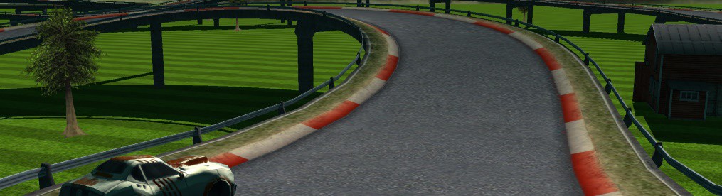
In my new 3D mobile racing game Diesel Racer 2 I have decided to use Shadow Volume as the technique for generating shadows in real time.
There are several reasons why I preferred this technique over shadow mapping.
Shadow mapping requires render targets. Apart from taking more texture memory some older mobile devices suffer a lot in performance when using render targets(and using them as texture resource).
Another reason is that it would be hard to get high resolution shadow maps on mobile GPUs.
Perhaps on more powerful devices, but I aimed to target weaker devices such as iPod 4th generation.
In short, with Shadow Volume you would need to generate the geometry that contains the volume of the shadow cast by an object.
You do so by creating fins from the edges that connect two triangles. One triangle is culled from the point of view of the light source and the other is not.
The collection of all those culled/unculled edge fins would then contain the volume of the shadow the light source cast from this object.
You would also need the caps of the shadow in order to have a complete closed geometry of the shadow volume but the caps are not always required when rendering the shadow volume.
Now that we have the shadow volume we can find the shadows it cast on the object by counting how many front faced fins minus how many back faced fins we have on every pixel on the object’s surface.
We would only count the fins that are visible to the camera and are not occluded by objects, or in other words, fins that pass the Z-Buffer test(in a specific pixel in the view).
If there are more front facing fins than there are back it means that the pixel is inside the shadow volume and thus the object casting the shadow occludes the light source for this specific pixel.
Z-Pass vs Z-Fail
The technique I described above is called the Z-Pass technique.
It works well enough unless the camera is inside the shadow volume.
In this case part of the volume fins are inside the viewing frustum and part of them are clipped.
Moreover, it may be that part of the fins are only partially inside the viewing frustum.
This will cause an under valued count of the amount of fins that are front facing the pixel and the amount of fins that are back facing.
One might suggests that you would add geometry on the front clipping plane of the frustum to accommodate for the fins that are behind the camera.
However, such geometry would be difficult to create especially since it’s rasterization might not sit perfectly with the partially clipped fin(with the front clipping plane of the frustum).
The reason this technique is called the Z-Pass technique is because we only count the fins that pass the Z-Buffer test or are not occluded by objects in the scene.
There is another technique called the Z-Fail(or “Carmack’s Reverse”).
Instead of counting the fins that pass the Z-Buffer test we could count the fins that fail the Z-Buffer test(the fins that are behind the objects in the scene).
The reason this works is because we are actually interested in the pixels on the surface of the scene’s objects and so it doesn’t matter much if we count the fins from one side of the surface or from the other side of the surface.
This will solve the issue of having the camera inside the shadow volume because Z-Buffer values are usually greater than 0(the front clipping plane{-1 for OpenGL}) and even if the Z-Buffer had values right on top of the front clipping plane, you wouldn’t see much anyway.
This technique requires that the shadow volume has caps in the end otherwise you would have ghost shadows since now the end of the shadow volume is more likely to be rendered(because it is more likely to be occluded by objects).
Rubinstein’s Fix for Z-Pass
We mentioned that in Z-Pass there is an issue when the camera is inside the shadow volume.
We also mentioned that we would could have fixed this issue if only we would create geometry on the front clipping plane that would negate the clipped fins or partially clipped fins.
However, that is not entirely true.
We don’t need to create geometry on the front clipping plane yet we can negate those back fins with no counterpart.
Lets say we have a closed mesh.
If we render this mesh with no Depth test(Z-Buffer test is set to always pass) and the camera is not inside it, then the front facing fins and the back facing fins will have to cancel each other and we would just get 0 as the total count of front facing fins minus back facing fins.
What if the camera is inside this volume?
Then we would get a negative count of all the missing or partially missing fins!
So in order to fix the issue of rendering inside a shadow volume with Z-Pass we would just need to render the shadow volume again but with no Depth test at all and adding the negative of the count!
The important thing to remember though is that in the fixing pass we need the shadow volume to be a closed shape(using caps).
Otherwise we would have ghosting shadows just like in the Z-Fail technique.
Broken Z-Pass Shadow
Rubinstein’s Fix
Final Fixed Result
Conclusion
The technique I presented could be an alternative to “Carmack’s Reverse”.
However, I am not sure how much more beneficial it is.
It probably has it’s own benefits and might be used for other things.
I am using this because it was easier for me to implement and because I wasn’t sure what was going on with the Z-Fail technique although now it’s easier for me to understand both.
In any case, I hope this article was beneficial for you.
p.p.s. the Shadow Fix technique might not be available on all platforms yet, it takes time to update versions.
Edit:
I was told on r/gamedev that this technique is almost identical to “Carmack’s Reverse”.
While “Carmack’s Reverse” is doing Depth Fail I am doing Always minus Depth Pass which ultimately is equal to Depth Fail since A = DP + DF.
However, in my method I could render only a small part of the volume mesh in Always. Rendering it with DF would require to render the entire thing as you also need to render the shadows instead of only fixing the DP.
Here are the two meshes I use. One for the visuals and one for Shadow Volume ‘A’ fix.
When packed to 4 bytes alignment this struct is 52 Bytes long.
However, when packed to 8 bytes alignment this struct is 56 bytes long! But in the file the header is saved to 52 Bytes and does not have 4 bytes of padding at the end like in memory.
The solution is to always read 52 Bytes from the file(unless one day we will have 128 bit systems?).
We can read it as is into the memory of the struct in 64 bit, since the alignment only adds 4 bytes to the end of the struct in this specific case.
Do note that byte alignment might add bytes in the middle of the struct in both 32 bits and 64 bits.
In 64 bit systems, Foo will be 16 Bytes long and the extra 6 padding bytes will be between a and b.
In 32 bit systems, Foo will be 12 Bytes long and will have 2 padding bytes in between a and b.
Apple has documents about what you need to consider when porting your app from 32 bit to 64 bit, too bad I forgot to read it before I submitted the first build.
Here is an example of a test normal map my artist created for the car(it doesn’t have a lot of details it’s just a test):
Test Normal Map
Memory Usage
When you load a texture into OpenGL it doesn’t matter how much space it takes on the disk, what matters is how much space it takes in memory.
For instance an image could be saved as a PNG and take only 700KB on disk but when loaded to OpenGL it would take 4MB because it’s a 1024×1024 32 bit RGBA uncompressed format.
In my racing game I would have 4 different cars, each one with it’s own normal map. If each normal map is a 1024×1024 RGBA uncompressed image, it would take 16MB of memory with just the normal maps!
We would like to reduce the memory usage of these textures.
Compressed Texture
OpenGL ES2 supports loading compressed texture using glCompressedTexImage2D.
In the case of iOS the native supported compressed texture format is PVRTC.
The advantage of these compressed formats is that they are stored compressed in the OpenGL memory and they are only decoded in real time. So the memory usage is only of the compressed texture size.
A 4 bit PVRTC always give you a compression of 1/8 of the uncompressed 32 bit RGBA bitmap.
While PVRTC is great for diffuse or color textures, with normal maps the compression of the texture make it seem like there are lumps on the surface.
PVRTC compressed normal mapped car.
We might be missing the point of making things look better when we have such artifacts on the surface of our car.
16 Bit 565 RGB
Our original texture is 32 bit RGBA per pixels. Which means we have 4 bytes per pixel of the image.
There are uncompressed formats that use only 2 bytes per pixel.
For instance GL_UNSIGNED_SHORT_5_6_5.
We only need RGB since we don’t use the Alpha channel in our texture.
What will happen if we store the xyz components of the normal inside 16 bit RGB instead of 24 bit RGB?
16 bit RGB normal mapped car.
Again, with the reduced accuracy of the normals the end result is not very good.
16 Bit Two Components Packing
Our normals are normalized to the length of 1. We can actually derive the z component of our normal from our x and y components using Pitagoras theorem.
We only need 16 bits to store the x and y components.
However, we do not have a pixel format of two 8 bit components.
We do have this format: GL_UNSIGNED_SHORT_4_4_4_4.
We are going to pack the two 8 bit RG components into the four 4 bit RGBA components of our new format.
if (Format==FORMAT_RG16_COMPRESSED)
{
	stbi_uc * Tmp = Data;
	Data = (unsigned char *)new unsigned short[w*h];
	unsigned int n = w*h;
	for (unsigned int i=0; i<n; i++)
	{
		unsigned char r = Tmp[4*i];
		unsigned char g = Tmp[4*i+1];
		unsigned short v = (unsigned short)r;
		v = v<<8;
		v+=(unsigned short)g;
		((unsigned short*)Data)[i] = v;
	}
	delete [] Tmp;
}
After packing the texture into 16 bits we need to change the code in our fragment shader to unpack the texel into a normal vector.
In this case we reduce the memory usage by half of the original 32 bit texture and we don’t compromise any quality.
We might be paying in GPU processing power since now our fragment shader is more complex.
However, I didn’t notice any difference in performance on my iPad New.
We also assume our z component is always positive so we cannot represent normals that go inward.
However, in most cases we do not need normals that go into the triangle or the surface.
16 bit packed normal mapped car.
Talk To Your Artist
Until now we were able to reduce the memory usage by a factor of 2 without sacrificing the quality.
However, this might not be enough.
There is another way to reduce memory usage and that is having the artist optimize the texture mapping.
In our case the bottom part of the car is rarely seen or is only partially seen.
We don’t need a lot of details in the bottom part of the car so the artist can allocate a much smaller area of the texture for the bottom part.
He might also separate the car into two surfaces(which means two passes) and to have different textures for each surface while the bottom part will have a much lower resolution texture.
In our game I have told the artist to reduce the texture size from 1024×1024 to 512×512 while taking into consideration that we don’t need a lot of details in the bottom part.
With both the 16 bit texture packing and the reduction of the resolution of the texture, we will get a factor of 8 in reducing the memory usage.
For my new mobile racing game I have implemented decals for a few reasons.
Decals are useful to add extra details to a mesh when it is impossible to include all the details with one big UV mapped texture.
They are also useful for adding extra details dynamically without having to change the texture of the mesh they are being added to.
In this article I am going to focus on how to calculate the decal’s geometry so it can be used inside your code in real time.
How to Derive a Decal From a Mesh
The decal geometry is derived from the mesh’s geometry we are adding the decal into.
What we want to do is to project a 2D rectangle(or any convex polygon) onto the mesh’s surface and cut out the geometry of the projected rectangle.
Think of it as like using a cookie cutter to cut out a shape from the dough only our dough does not have to be flat.
A mesh in our case is made out of triangles.
What we want to do is cut all the triangles using our 2D rectangle(or “cookie cutter”) and then add the resulting triangles to our vertex buffer so we could send it for rendering.
We could go over all the triangles in our mesh and cut them one by one.
However, most of the triangles will be cut out completely so it will be a wasteful process.
In order to cut out the geometry from the mesh’s surface using our convex shape we use 3D planes to cut out each triangle.
This is the reason why we can only cut a convex shape using this method.
Each edge in our “cookie cutter” shape will be represented by a plane that it’s normal is the cross product of a vector on the edge and a vector that represent the direction of the projection.
So the edge and the vector that represents the direction of the projection are both contained by the plane.
When we cut a triangle using a plane we keep the part of the triangle that is on one side of the plane and we throw the part of the triangle that is on the other side.
It is possible that the triangle is completely thrown away or kept whole.
There are two scenarios in the case where the triangle is cut into a smaller piece.
Either the piece that we keep is made out of the “tip” of the triangle(and hence made out of one triangle), or it is made out of the “base” of the triangle. And thus it is a quad and is made out of two triangles.
When I say “base” and “tip” it could be relative to any of the 3 vertices of the triangle.
A possible algorithm would be:
1) Find all relevant triangles.
2) If relevant triangles list is empty go to (12)
  3) Add top relevant triangle to cutList
  4) If cutList is empty go to (10)
    5) Get next plane in the convex shape and cut the triangle into 0 to 2 triangles.
    6) Add the cut out triangles(if any) to the cutList.
    7) If didn't reach end of plane list go to (4)
  8) Add cutList triangles to finalGeometry list(if any).
  9) clear cutList
  10) Pop top triangle of relevant triangles list.
  11) go to (2)
12) Finish (finalGeomtry list contain all the relevant triangles).
UV Mapping of The Decal
There is another issue we didn’t even talk about.
The decal need it’s own UV coordinates. It cannot use the mapping of the mesh since they are mapped over the entire mesh and we want to map an entire texture into our decal.
I will explain briefly how to calculate the UV coordinates for a quad based decal.
The UV coordinates correspond to the projection.
Each one of the 4 vertices in our quad will be mapped to 4 UV coordinates on the texture space.
However, when we cut the mesh’s triangles using planes we might get vertices that are anywhere in between and inside the projection of our quad.
In order to calculate the UV coordinates we would need to project the new decal vertices back into the plane of our quad(or back into the “cookie cutter”).
Our projection is orthogonal and in our case it is in the direction of (0, -1, 0) so in order to project vertices back to the quad we simpley drop the y component.
If our quad was a rectangle we could have calculated the UVs from the distance of the projected vertex to the edges of the rectangle.
However, we want to solve this for a generic quad.
In order to do this we solve the following set of equations:
p = (v1*(1-t1)+v2*t1)*(1-t2)+(v3*(1-t1)+v4*t1)*t2;
This is a set of two equations where t1 and t2 are our variables(what we are trying to find), p is a 2D vector which is the point we projected back to the quad and v1, v2, v3 and v4 are 4 2D points of the quad itself.
To solve this we need to express t2 using t1 with one equation and then assign t2 to the other equation.
Then we will get a second order equation in t1.
However, we are suppose to get only one solution, right?
Well without getting into the details, we just need to get the most positive solution or just reduce the equation into a first order equation(where the factor that multiplies t1*t1 is nearly zero).
(Edit: We need to get the solution that is inside or closest to (0..1).
We do this by using the solution that is closest to 0.5.)
What will guide you which equation you need to solve is by testing every place that divides by an expression that it is not zero and test that a Square root is not negative.
When those expressions are zero(in the case of division) or negative(in the case of the Square root) you will know which equation you need to solve.
For each vertex in the decal you get it’s UV coordinates from solving the set of equations for the respective projection of the vertex into the quad(our p).
t1 and t2 are our UV coordinates.
Rendering The Decal
We render the decal in a separate pass than the mesh itself.
We would use similar shaders to the mesh but we would also use a blend mode to blend the decal into the mesh.
For instance normal blending but otherwise rendering the decal is very similar to rendering the mesh.
There is another difference though. Since the decal is derived from the mesh geometry, it will cause Z Fighting in the Z Buffer.
In order to have our decal render over the mesh we need to offset the decal’s depth.
In GLES2 we have a method called glPolygonOffset that does that.
For the sake of completion here is the relevant source code: